Home Made CDI project

Eoin70

Well-Known Member
ive started to Build a CDI from the bottom up,
its quite a simple design including one PIC 12F629 microcontroller, one Opto-Coupler and one BTX 18 SCR there is also lots of little tricks for keeping the high voltage stuff away from the IC's.

Ive calculated the delays by hand and there is a new delay for an increment of 100 rpm, my micro does not have muhc memory so im limited to that

But soon ill switch to an external eprom where i can hold many many curves
if you want the Source C code just ask ;)

[ir]http://i27.photobucket.com/albums/c178/eoin_1987/IMG_0180.jpg[/ir]

Its only on breadboard now but soon its going to be on a PCB

[ir]http://i27.photobucket.com/albums/c178/eoin_1987/IMG_0179.jpg[/ir]
 
Last edited:
Advertisement - register to remove this

Looks good.

Are you gonna build your own ignition system too?
I have the drawings for a Hall-type system, wich convert 12 volt into around 30kV.
But how to connect the CDI and the rest of the system together, is out of my knowlegde.

/Swobber who just scored 10 in Ignition systems (On the 13-scale - Running 00,03,5,6,7,8,9,10,11 and 13).
 
No need to make my own stator and rotor,
at the moment my triggering point is at 72degrees before the TDC
now at high rpm im having a spark at 36 after this point
and at low rpm its about 5o degrees After the trigger point
 
So the more RPM's, the early'er ignition spark?


I asked the question because with a Hall or Inductive signal you can make the flywheel as small as you want to and seriously light too.

/Swobber
 
I've made one myself some years ago. :)
It's a simple one, it sparks immidiately after it's triggered.
It was just an experiment to check my thoughts.

[IR]http://members.home.nl/jdvrielink/IMG_0116.JPG[/IR]


Eoin70:
How do you trigger the cdi?
With an external pick-up (like the original ignition) or do you look at the sinus (like selettra, hpi, etc.)?
And whats the value of the capacitor, it looks huge. :p
 
its a 2uf capacitor i dont know why its so damn big
there was a big problem where when the SCR would trigger it would actually increase the ground rail voltage a huge amount, this fried many many parts

its for use with a Minarelli ignition, but soon im gonna make my own trigger and rotor and have an external 300v to charge the cap
do you think for the capacitor charging voltage thats its best to fully bridge rectify it?
at the moment its just half wave rectified ;(
 
A full bridge charges the capacitor faster.
At my circuit the full bridge is also used half because of the configuration of the ignition coil (central ground).

Your capacitor looks like one for a 1-fase electric motor.
 
Jasper V said:
A full bridge charges the capacitor faster.
At my circuit the full bridge is also used half because of the configuration of the ignition coil (central ground).

Your capacitor looks like one for a 1-fase electric motor.
thats exactly it, the cap is called a Motor run capacitor ;)
it is far better than any electrolitic cap !!

ive found that 2uf works very very well
at the moment i have a look up table for the curve, but next im going to calculate a formula to have a different delay for every single rpm.

but there a problem in that, i need to do a floating point division which i dont think an 8 bit pic is very good at :(

here's my future timing curve , please note the trigger is at 72degrees before TDC
[ir]http://i27.photobucket.com/albums/c178/eoin_1987/TimingCurve.jpg[/ir]
 
Last edited:
ive started to Build a CDI from the bottom up,
its quite a simple design including one PIC 12F629 microcontroller, one Opto-Coupler and one BTX 18 SCR there is also lots of little tricks for keeping the high voltage stuff away from the IC's.

Ive calculated the delays by hand and there is a new delay for an increment of 100 rpm, my micro does not have muhc memory so im limited to that

But soon ill switch to an external eprom where i can hold many many curves
if you want the Source C code just ask ;)

[ir]http://i27.photobucket.com/albums/c178/eoin_1987/IMG_0180.jpg[/ir]

Its only on breadboard now but soon its going to be on a PCB

[ir]http://i27.photobucket.com/albums/c178/eoin_1987/IMG_0179.jpg[/ir]

can send the circuit diagram and the hex code. to do in my motocycleta?

thanks
 
thats exactly it, the cap is called a Motor run capacitor ;)
it is far better than any electrolitic cap !!

ive found that 2uf works very very well
at the moment i have a look up table for the curve, but next im going to calculate a formula to have a different delay for every single rpm.

but there a problem in that, i need to do a floating point division which i dont think an 8 bit pic is very good at :(

here's my future timing curve , please note the trigger is at 72degrees before TDC
[ir]http://i27.photobucket.com/albums/c178/eoin_1987/TimingCurve.jpg[/ir]

This ignition is build for 4 stroke??

Because at 2 stroke engine, the higher the rpm the closer the timing is to the TDC
and at lower rpm the timing is much more before the TDC
 
nice cdi.

here's also a nice site about building cdi's (including programmable cdi's)
http://www.transmic.net/

a schematic drawing of a cdi unit with a fixed sparking point, without retarding or anything (I heard red selletras also use a fixed point)

http://www.transmic.net/images/schema1.gif

this cdi required a pickup coil, wich connects to J2, and the value of R1 may verify with different ignitions (yz125 ignition = 150kOhm)

I hope someone can help me: I 'd like to build a CDI for my 1987 yz 250 which is a motocross bike, so it doesn't have lighting system.

I've tryed to build the analog CDI which is present on the website you specified, but it doesn't work, I have no spark at all. Probably, because in this schema:
http://www.transmic.net/analog/cdi_ana_sch.pdf
I'm not able to understand what I have to connect to PAD3 and PAD4.

I just have a stator with three wires which I use for PAD5, PAD6 and PAD7.

Actually, I don't know if that schema can work well also on my yz250 which is from the same year.

I've read that you know when you bike do the spark and at what degrees. How you are able to have this information?
Do you use an oscilloscope or what? Can you explain me the procedure, please?

Can you give me some advices in order to have a working CDI for my bike, please?

Thanks a lot.

You connected wrong way the wires. I dont know what is your stator. If you upload one picture I could help you. But If you only have 3 wires, the logical case is you have:
1- ground
2- power from stator
3- pickup sensor.

Some stator doesnt have external pickup and use the same wave of stator to trigger the tyristor. So I believe you should check:

If you have multimter, check the the wire continous to ground and put in PAD4, the another wire to PAD3 and PAD5 for the wire from pickup sensor, you can check it since it is square plastic attached to stator, if you have one.
PD2 to ground chassis.
PD1 to high coil .

For fix the igntion. You will have one mark between stator-rotor. Fixed this point you can measure the milimeters from tdc, so if you know the stroke you can calculates the mm down the piston to any fixed grades (16-20ºbtdc).

Thanks a lot for your help, josearrow!
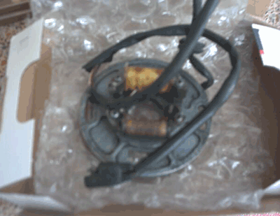
This is a picture of my stator:
statore_yz.png


I changed these two coils with some new ones one years ago.
I don't have an external pickup, I just have a small coil (pickup) which is about 50 Ohm, and another bigger coil (the source) which is about 170 Ohm.
And my stator has just three wires.

I'll try to do the connections you suggested to me, but I have to connect nothing to PAD6 and PAD7?

My bike has no signal to control the spark during the idle?
In this way, I don't need the R3 variable resistor, isn't it?

I'm also having problems with the correct connection of the T1, I've read its datasheet and I'm not able how to connect its pins because I don't know which pin is the base and which is the collector.

I'm trying to use this CDI because my bike runs great but after few minutes it shut off like if there is no spark anymore. Then it run again if I try to start it after few time, it goes well but then it shut off again.
It happens the same thing with my old CDI. This is the third CDI that I'm chainging and I'm not able to find other CDI anymore. I really hope that this CDI will work.

EDIT: I used a multimeter and I can see continuity between two wires from the stator with the frame. I thought there was only one wire to be in continuity with the frame..
 
Last edited:
Back
Top